Project - Making an RPM Meter
- automatelabonline
- Apr 3
- 4 min read

Microcontrollers are compatible with several types of sensors. In general, reading these sensors is easy to implement, requiring only reading an analog port or using some communication protocol to collect the data. However, rotation sensors generally do not have such automatic implementation. This post will explore the development of a project that reads an RPM meter.
Explaining the Problem
Most sensors used to measure RPM send pulse signals when the shaft completes a revolution. In general, something is used to signal to the sensor that the revolution has been completed, such as a reflective strip or a protrusion on the shaft. The sensors used for RPM are generally of the following types:
Reflective: Sends a light signal and captures the return of that signal. A reflective tape is placed on the rotating shaft, causing the light signal to return only at a specific position.
Capacitive: Captures the capacitance of nearby objects. Acts as a proximity sensor. When there is something near the front of the sensor, it sends positive voltage; when there is nothing, it sends zero voltage. A protrusion is made on the shaft to get closer to the sensor when it completes its rotation.
Inductive: Captures the inductance of nearby objects. It works in a similar way to the capacitive sensor, but only works for metals.
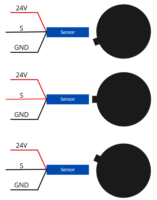
The image below exemplifies the behavior of inductive/capacitive sensors. The signal (S) usually presents a low logic level. When the relief passes through the sensor, the logic level of S goes high, and then returns to low. In other words, a high logic level pulse is generated in the sensor signal.
NPN and PNP sensors
It is important to highlight the difference between PNP and NPN type sensors.
PNP sensors are in a high impedance state. When an object approaches the sensor (or light is reflected, in the case of a reflective sensor), this signal goes to a high logic level (24V). In other words, when there are no objects nearby, the sensor does not go to a low logic level, but instead remains in a high impedance state. This state basically means that there is a high resistance between the signal and the 24V. Therefore, for the signal to actually go to GND, it is necessary to build the system so that the signal is forced. An example is the case below.

By adding a resistor between the signal and GND, the signal is forced to a low logic level when there is no object detected by the sensor, and will still remain at 24V when the sensor detects something.
The case of the NPN sensor is similar. However, when it detects an object, it generates a pulse in GND. In other words, it is necessary to force the signal to be at 24V the rest of the time. To do this, the following circuit can be used:
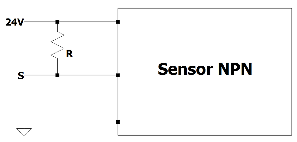
The resistor value can be high, since the current passing through it must be as low as possible. This reduces power consumption.
Going from 24V to 3.3V / 5V
Most sensors use 24V. However, this voltage is not compatible with most microcontrollers. To fix this, it is necessary to make a circuit that will transform the 24V/GND pulses into 3.3V/GND pulses or into 5V/GND. It will be shown the case for 3.3V, but this circuits wotk with 5V too. The following circuits are used for this:
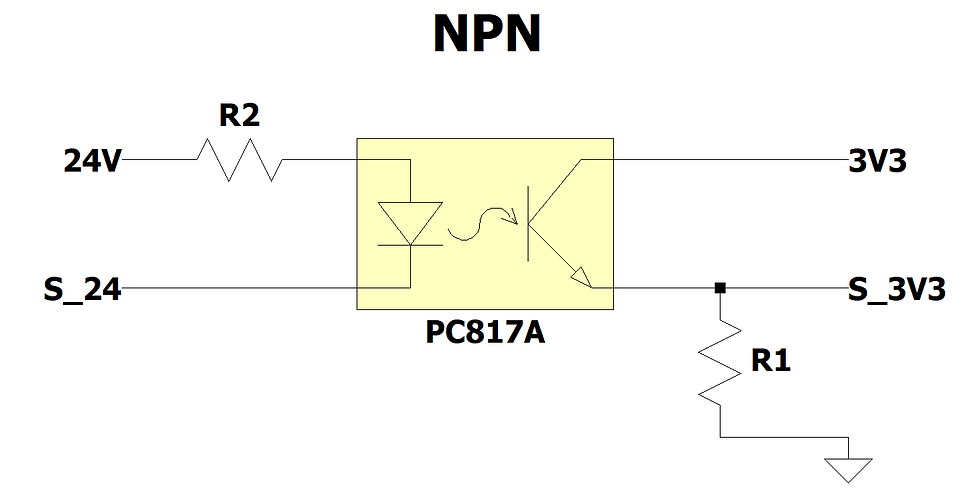
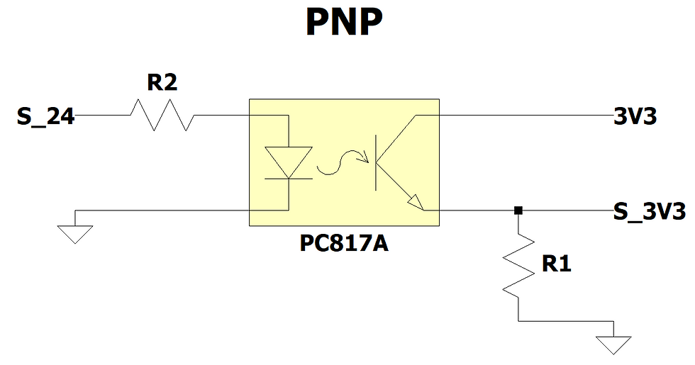
S_24 represents the signal coming directly from the sensor. S_3V3 is the signal that will be directed to
Both circuits use a PC817 optocoupler, this component is responsible for "transforming" the 24V signal to 3.3V. When there is a current passing between the left terminals, the right terminals will short circuit, causing the S_3V3 signal to go to 3.3V. As soon as the left current stops, the right terminals are opened, interrupting the current on that side as well and causing S_3V3 to go to GND. With this connection scheme, it is not necessary to place the resistor shown in the images from the previous section.
As for the resistors, the value of R2 should be high, because the higher its resistance, the lower the current consumption. For R1, a higher value is also recommended, but with caution. Increasing the value of R1 too much ends up slowing down the system, and causes the circuit to not read very high frequencies correctly. We recommend testing with 10kΩ to start. The PC817 component supports up to approximately 80kHz.
Code for Rpm meter
#define PIN 2

unsigned long lastTime;
int rpm;

void rpmInterruption() {
	unsigned long currentTime = micros();
	rpm = 60000000 / (currentTime-lastTime);
	lastTime = currentTime;
}

void setup() {
	Serial.begin(9600);
	attachInterrupt(digitalPinToInterrupt(PIN), rpmInterruption, RISING);
	lastTime = micros();
}

void loop() {
	Serial.println("rpm = " + String(rpm));
	delay(10000);
}
The code above calculates the rpm from the time difference between two pulses. To do this, an interrupt was created on a pin. The S_3V3 signal shown in the circuit above must be placed on this pin.
Whenever a rotation of the measurement object occurs, a pulse is sent to this pin, which calls the rpmInterruption() function. In this function, the rpm is calculated using the following formula:
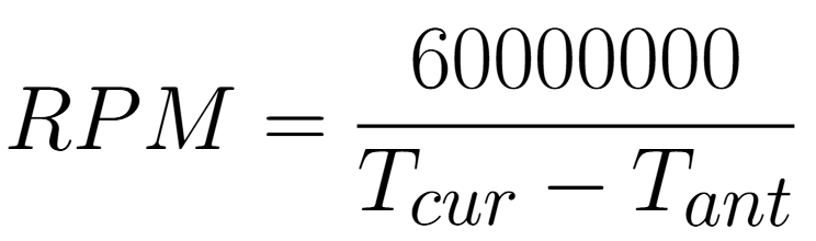
where Tcur represents the current time and Tant the time of the last pulse, both in microseconds. Therefore, Tcur - Tant represents the time interval between the last two pulses. The number above the fraction is the number of microseconds in one minute (60 million). It is used to convert to revolutions per minute. If you want to convert to Hz, you can replace this value with 1000000 (1 million).
The loop() function writes the rpm value to the Serial every 10 seconds.
Opmerkingen