Introduction to ESP32
- automatelabonline
- Feb 15
- 6 min read

Updated: Feb 21
ESP32 is a series of microcontrollers produced by Espressif Systems. With 512KB of SRAM and processing speeds of 160 or 240 MHz, the focus of ESP32 boards is to combine functionality with low energy consumption. There are single-core versions and, mostly, dual-core versions. The ESP32 is widely used in IoT and automation projects due to its native Wi-Fi and Bluetooth capabilities. The main peripherals available are:
Up to 18 Analog Inputs (ADC) | Capable of reading voltages between 0V and 3.3V, with a 12-bit resolution |
2 Analog Outputs (DAC) | Having an 8-bit resolution and generating real analog voltages |
Up to 16 PWM channels | Pulse Width Modulation channels, simulate analog voltages and have a 16-bit resolution |
Up to 10 touch pins | Ports with capacitive touch detection |
Various communication interfaces. | Interfaces for SPI, I2C, I2S and UART communication |
Furthermore, all the pins of the ESP32 support interrupts, except GPIO 6 and GPIO 11. Interrupts pause the code when a digital pin changes state, and then execute a specific function. This functionality is very useful for creating systems that react in real-time.
It is important to emphasize that there are several models of ESP32 boards, each with different pinouts and functionalities. Therefore, different boards may or may not have certain features. One of the most common models is the ESP32 DevKit v1, which has 30 pins. Below is a diagram of the pins for this model.
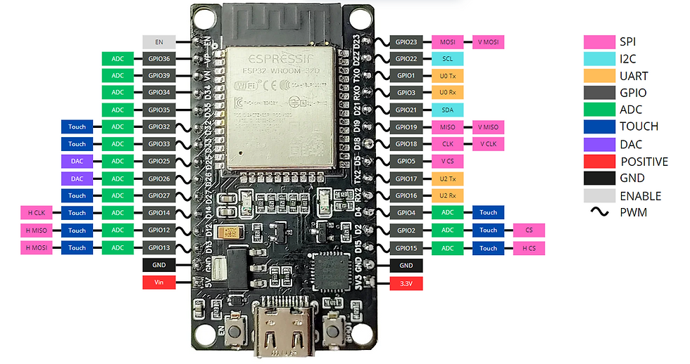
SPI
SPI (Serial Peripheral Interface) is a communication protocol that enables the creation of a communication network between the microcontroller and various other components. The ESP32 features 3 SPI interfaces, named SPI, VSPI, and HSPI. Each of these interfaces uses 4 pins for information exchange: MISO, MOSI, CS and CLK.
I2C
I2C (Inter-Integrated Circuit) is another widely used communication protocol for data exchange between microcontrollers and modules. The ESP32 features an interface for I2C communication, using pins 22 (SCL) and 21 (SDA).
UART
UART (Universal Asynchronous Receiver/Transmitter) is another communication protocol. The ESP32 contains 3 UART interfaces, which are:
UART0 - Used for code upload and serial monitor. It uses pins 1 (TX) and 3 (RX). These pins cannot be changed. It can be used for communication with other devices, but it is typically used only by the serial monitor.
UART1 - Used by the Flash memory. It is necessary to change its pins to be used for communication with other devices.
UART2 - Free for use. It uses pins 17 (TX) and 16 (RX). These pins can be changed.
GPIO
These refer to the terminals of the ESP32 microprocessor. Not all of the processor's ports are available as pins on the board. Depending on the board used, the available GPIOs may change, but their functions will always remain the same. For example, some boards may not have GPIO15, but on all boards where this pin exists, its function will be the same.
It is important to emphasize that the ESP32 is just the microcontroller chip, shown in the image below. The ESP32 DevKit v1 is a development board that uses the ESP32 microcontroller. However, for simplicity, the development board is commonly referred to simply as the ESP32.

ADC
These are the ports where analog-to-digital conversion of the signal can be performed. It is possible to measure voltages between 0V and 3.3V, with a resolution of up to 12 bits. This resolution can be changed via code.
TOUCH
These represent the capacitive touch pins. These pins can detect when capacitive charge, such as a finger, approaches. They can be used as digital inputs or to wake the ESP32 from power-saving mode.
DAC
These are the true analog outputs of the board. They generate an analog voltage between 0V and 3.3V with 8 bits of resolution. The pins with this function are 25 and 26.
Power Pins
There are 3 ways to power the ESP32:
Through the 5V from the USB cable.
Using 3.3V on the 3V3 terminal.
Using between 3,3V e 12V on the Vin terminal.
The ESP32 has a voltage regulator on the Vin pin, which supports up to 12V. However, it is not recommended to use such high voltages, with the maximum recommended being 5V.
If you choose to power the board through the Vin pin or the USB, the 3V3 pin will represent the regulated voltage, meaning it will be 3.3V. This pin can be used as an auxiliary power source to power other components.
Enable
The Enable pin allows for the reset of the board. When this pin is connected to GND, it disables the voltage regulator and turns off the board.
PWM
The PWM pins allow for pulse width modulation of the signal. The output signal alternates between 3.3V and 0V at a high frequency. The proportion of time the signal stays at 3.3V determines the output voltage. For example, if the signal stays at 3.3V for 50% of the time and at 0V for the other 50%, the output voltage will be 1.65V, half of 3.3V. Thus, thttps://www.automatelab.online/post/introdução-ao-esp32hese pins simulate analog outputs, which is sufficient for many applications.
Buttons
The ESP32 boards have two buttons, labeled EN and BOOT. The EN button connects the enable pin to GND, causing the board to restart. The BOOT button puts the board into download mode. Sometimes, it may be necessary to hold this button during the code upload.
Programming the ESP32
To program the ESP32, we will use the Arduino IDE software. We have a tutorial on how to set up your programming environment for ESP32 boards here on the website. You can access it through this link.
When you start the program, a new project will be created.
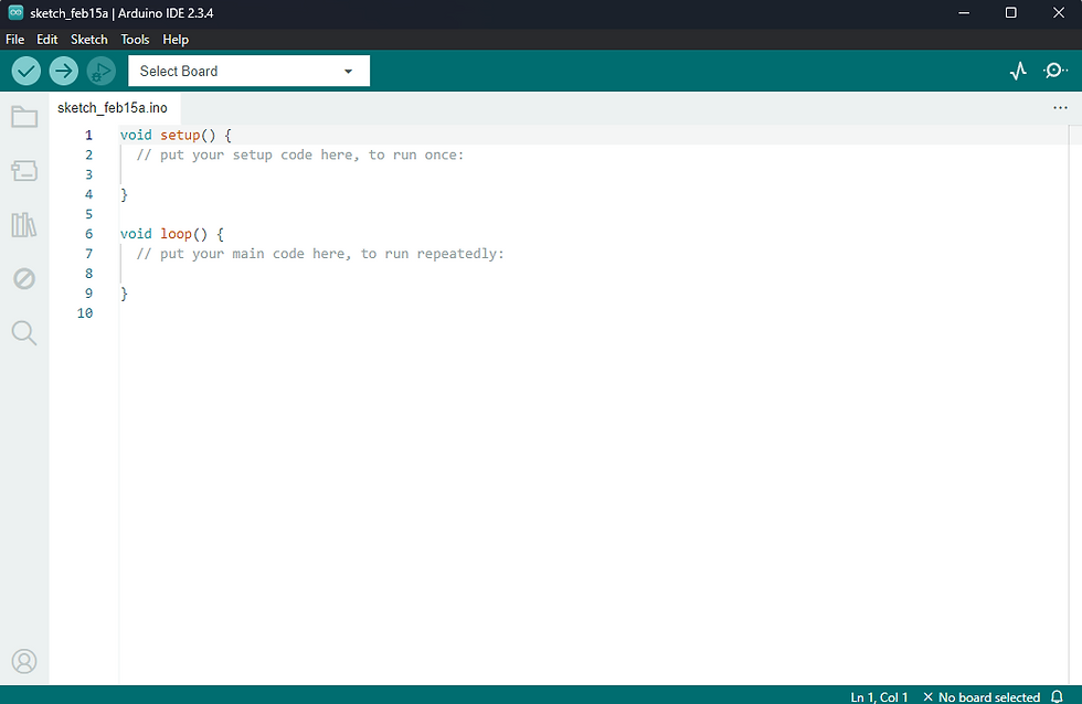
In this project, there are two functions (void). The setup() function will be executed only once when the board is powered on. In this function, the initial configurations of the board are made. The loop() function, on the other hand, will run repeatedly during the operation of the board.
Let’s create a simple code where the ESP32 writes the message "Hello World!" every second through the serial monitor.
void setup() { // code that will run just once
  Serial.begin(9600); // begins the Serial with a baudrate of 9600 bps
}

void loop() { // code that will run repeatedly
  Serial.println("Hello World!"); // print "Hello World!"
  delay(1000); // wait 1 second
}
Explaining the Code
In the setup function, which runs only once when the board is powered on, there is the following line of code.
Serial.begin(9600);This line starts the Serial monitor, or in other words, the communication between the ESP32 and the computer. The number in parentheses, 9600, represents the baudrate of the communication. The baudrate, in simple terms, is the data transmission rate. In other words, the higher the baudrate, the faster the communication between the ESP32 and the computer tends to be.
In the loop function, there are two lines.
Serial.println("Hello World!");This line sends the message "Hello World!" through the Serial. The function Serial.println() adds a line break at the end of the message. So the next message sent will be displayed on the next line. If this is not desired, you should use the Serial.print() function instead. This way, no line break will be added.
The next line calls the delay() function.
delay(1000);This function makes the ESP32 wait for a specified amount of time before proceeding with execution. The time is given in milliseconds. In this case, 1000ms = 1s, meaning the board will wait 1 second before continuing with the program.
Running the Code
By clicking the arrow button in the upper left corner, the code will be uploaded to your board. Make sure the board model and serial port are correctly selected for the code upload. If you have any doubts, check the tutorial at this link.

To open the serial monitor and check the messages sent by the ESP32, simply click on Tools -> Serial Monitor in the top menu.

This will open the serial monitor at the bottom of the Arduino IDE. There, you will be able to see the messages appearing every 1 second, as configured in the code. Make sure the Serial Monitor is set to the same baudrate as the board. This can be configured in the right corner of the Serial Monitor tab.

Conclusions
The ESP32 is undoubtedly one of the most powerful and versatile boards available on the market, offering impressive features such as Wi-Fi, Bluetooth, multiple processing cores and a wide range of peripherals. This combination of performance and connectivity makes the ESP32 an excellent choice for those looking to explore the world of automation and the Internet of Things (IoT).
Learning to program it opens up a range of possibilities, from simple home automation projects to more complex and connected systems. With knowledge of the ESP32, you'll be ready to create innovative solutions, integrate devices and improve process efficiency. This learning not only enhances your skills in electronics and programming but also places you at the forefront of the technologies that are shaping the future of automation.

Commentaires