Introduction to Electronics - Resistors
- automatelabonline
- Feb 23
- 4 min read

Updated: Feb 25
Resistors play a fundamental role in electronics. This type of electrical component is one of the simplest to understand, and having a proper understanding of it is essential for anyone who wants to delve deeper into the field of electronics.
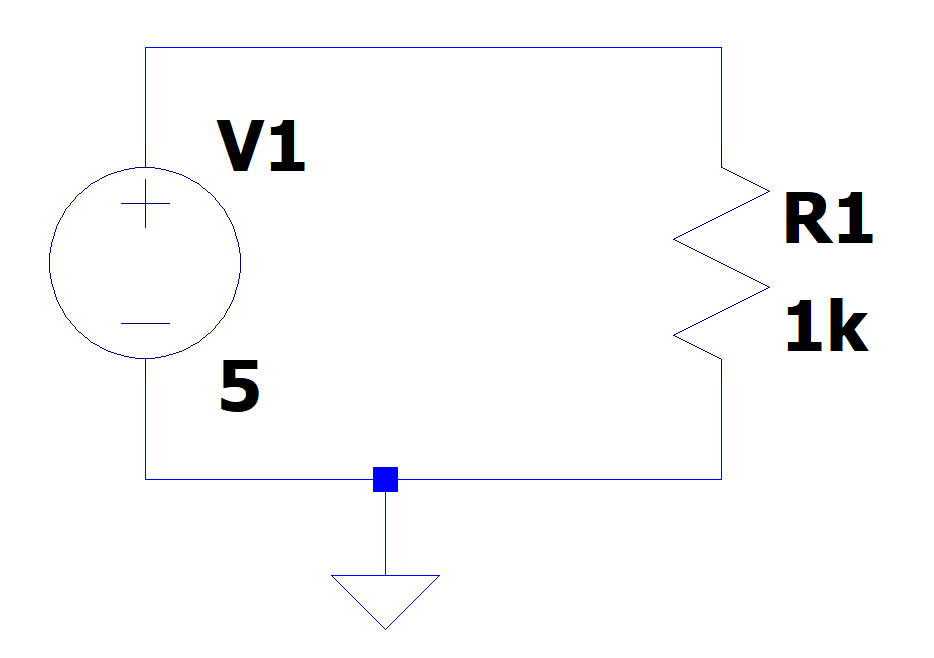
Within an electrical circuit, resistors are responsible for, as the name suggests, creating resistance to the flow of current. In circuit schematics, resistors are represented by a zigzag pattern, as shown in the figure below. R1 represents a 1kΩ resistor.
The formulas that mathematically explain the operation of resistors are called Ohm's Laws.
Ohm's Laws
1st Ohm's Law
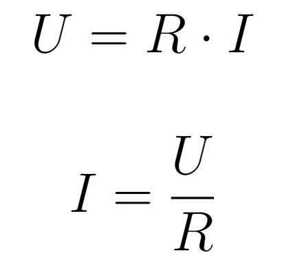
The first Ohm's Law addresses the relationship between voltage, resistance and current. According to this law, the current passing through a resistor is directly proportional to the voltage applied across its terminals. In other words, if twice the voltage were applied, twice the current would pass through the component. The main formula to understand this relationship is:

In this equation, R represents electrical resistance, U represents the applied voltage, and I represents the generated current. Other variations of this same equation are:
This equation assumes that resistors have linear behavior. In this context, the value of electrical resistance acts as a proportional factor between voltage and current.
For example, applying 5V to a 1Ω resistor will generate
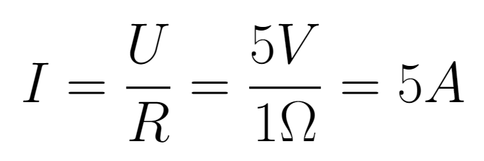
The multiplication factor between voltage and current is 1, as 5V generates 5A. However, when applying the same voltage to a 10Ω resistor, the generated current will be:
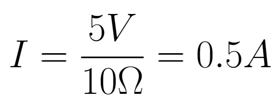
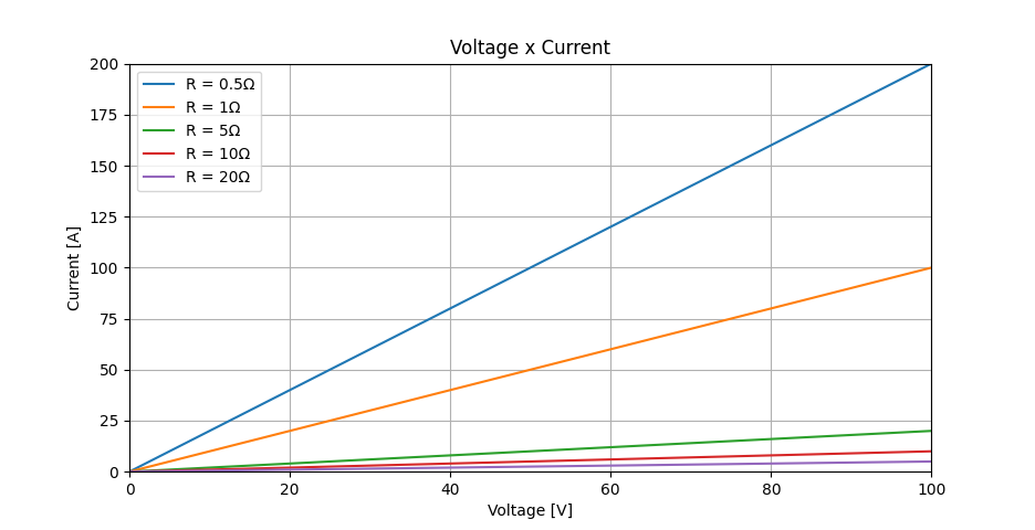
Now, the factor between voltage and current is 10, as 5V generates 0.5A. This behavior can be better understood by evaluating the U x I curve for different resistance values. The slope of the line decreases as the electrical resistance increases.
2nd Ohm's Law
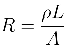
The second Ohm's Law addresses the calculation of electrical resistance in resistors. According to it, resistance is affected by three parameters, which are:
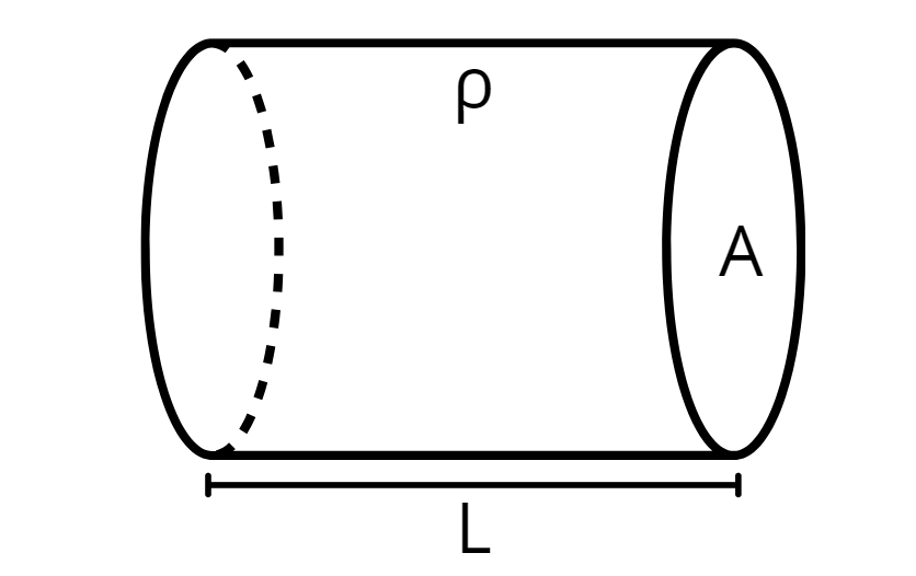
Resistivity of the Material (ρ) - This is an intrinsic property of the material from which the resistor is made. It is measured in Ω⋅m.
Cross-sectional Area (A) - This is the area through which the current can pass. It is measured in m².
Length (L) - This is the length of the wire/resistor. It is measured in meters (m).
The formula that describes the resistance as a function of these parameters is:
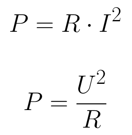
Consumed Power
Using the first Ohm's law and knowing that the power consumed by an electrical circuit is given by:
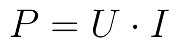
It is possible to obtain the two expressions below for the power consumed by a resistor.
Real Resistors
The most common types of resistors have a cylindrical shape and feature several color bands. These bands help to identify the value of the electrical resistance and its tolerance.
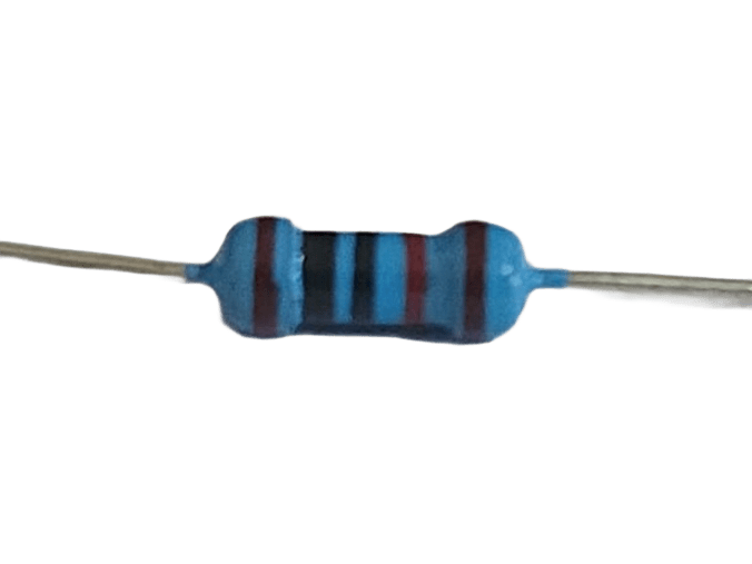
Resistors have 4 or 5 color bands, and each band serves a specific function. The table below shows the function of each band.
The first two bands represent the first two digits of the resistance. A third band may be added in some cases to provide more precision, but it doesn't always appear. For example, if the first three bands are Brown, Black, and Black, they would represent the number 100.
The fourth band is used as a multiplier. This value should be multiplied by the value of the previous 2 or 3 digits to obtain the full resistance. Continuing with the previous example, if the fourth band were Yellow, we would have 100 x 10k = 1MΩ.
The last band represents the tolerance of the resistor, or its maximum error. The most common values are 5% and 1%. However, in some applications where precision is important, it is possible to find resistors with smaller tolerances.
Color | 1st Band | 2nd Band | 3th Band (optional) | Multiplier | Tolerance |
Black | 0 | 0 | 0 | 1 | |
Brown | 1 | 1 | 1 | 10 | 1% |
Red | 2 | 2 | 2 | 100 | 2% |
Orange | 3 | 3 | 3 | 1k | |
Yellow | 4 | 4 | 4 | 10k | |
Green | 5 | 5 | 5 | 100k | 0,5% |
Blue | 6 | 6 | 6 | 1M | 0,25% |
Violet | 7 | 7 | 7 | 10M | 0,1% |
Gray | 8 | 8 | 8 | 0,05% | |
White | 9 | 9 | 9 | ||
Gold | 0,1 | 5% | |||
Silver | 0,01 | 10% |
Resistor Association
Series Connection
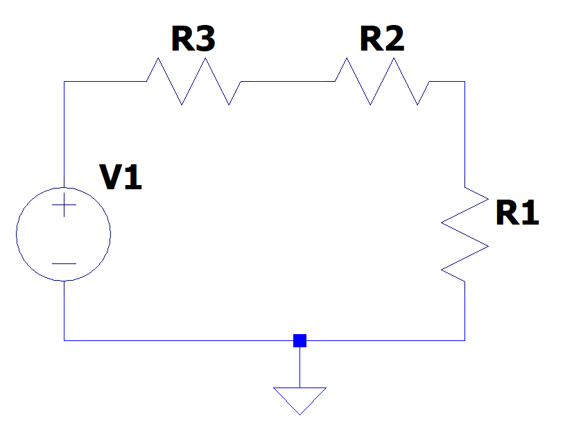
It is possible to combine resistors in more complex circuits in order to achieve desired behaviors. In the example below, we have resistors connected in series. The current passes through all the resistors at once, but the voltage is divided among the three.
The equivalent resistance of the resistor association in this format is given by:

In other words, when resistors are connected in series, the equivalent resistance will increase. The current passing through the circuit is the same through all resistors, as the current has only one path to follow.
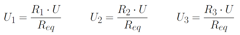
The voltage across each component is not the same. The voltage will be divided among the resistors so that, the higher the electrical resistance, the higher the voltage. The equations for the voltages across the 3 resistors are:
Parallel Connection
When resistors are connected in parallel, the voltage applied across all of them is the same, but the current is not.
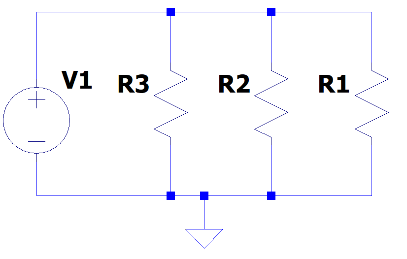
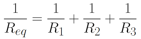
This type of connection can be thought of as creating 3 paths for the current to flow through. In other words, adding more resistors in parallel will make the equivalent resistance decrease, as more paths for the current will be created, and consequently, more current will flow through the circuit. The formula for the equivalent resistance of parallel connections is:
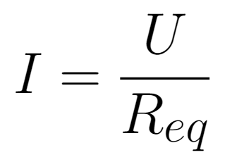
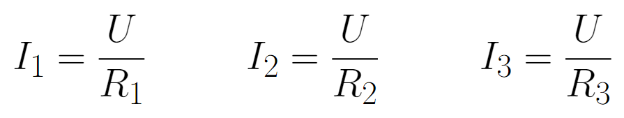
The electric current that passes through each resistor can be calculated using:
Conclusions
In conclusion, resistors play a fundamental role in electronic circuits. Understanding the basic concepts related to resistors, such as resistance, Ohm's Law, and types of resistors, is crucial for effectively designing and analyzing circuits.
By mastering these concepts, it is possible to optimize the performance and safety of electrical systems, ensuring greater efficiency and reliability. The importance of resistors is undeniable, and their continuous study is essential for the evolution of electronic technologies.


Comments