Introduction to Arduino Uno
- automatelabonline
- Feb 15
- 6 min read

Updated: Feb 21
Arduino is an open-source electronic prototyping platform widely used in the development of automation projects and interactive systems. Created in 2005 by a group of researchers from Italy, led by Massimo Banzi, Arduino emerged as an accessible solution for students and electronics enthusiasts, allowing them to easily develop their own inventions. The name "Arduino" comes from a local tavern in Ivrea, the Italian city where the project began.
The Arduino platform is based on microcontrollers that can be programmed to interact with sensors, motors and other electronic devices. Its ease of use and the vast community of developers have made Arduino a popular tool in various fields such as education, robotics, home automation and interactive art.
Among the most famous Arduino board models, the following stand out:
Arduino Uno: The most popular and widely used model, ideal for beginners and basic projects.
Arduino Mega: A version with more input/output pins, ideal for more complex projects that require greater connectivity.
Arduino Nano: A compact version, perfect for prototypes that require a more reduced design.
Arduino Leonardo: With the ability to function as a USB device, allowing it to be recognized as a keyboard or mouse.
Among these boards, the Arduino Uno models stand out. Not only because they have several useful features for enthusiasts and professionals, but also due to their affordable price. It is an excellent option for those who wish to begin in the world of prototyping with microcontrollers.
In the figure below, the pinout of the Arduino Uno board is shown.

The Arduino Uno boards feature:
6 Analog Inputs | Capable of reading between 0V and 5V with 10-bit resolution. |
A variety of communication interfaces. | Interface for UART, I2C, and SPI communication. |
13 digital I/Os | They can be configured as digital inputs or outputs. |
6 pins with PWM output. | Pulse Width Modulation channels, simulate analog voltages, and have a 8-bit resolution. |
SPI
SPI (Serial Peripheral Interface) is a communication protocol that allows the creation of a communication network between the microcontroller and several other components. The Arduino Uno features 1 SPI interface, using 4 pins to exchange information: MISO, MOSI, CS, and CLK.
I2C
I2C (Inter-Integrated Circuit) is another communication protocol widely used for data exchange between microcontrollers and modules. The Arduino Uno features an I2C communication interface, using pins 18 (SCL) and 19 (SDA).
UART
UART (Universal Asynchronous Receiver/Transmitter) is another communication protocol. The Arduino Uno contains a UART interface, using pins 0 (RX) and 1 (TX).
DIGITAL PINS
These are the digital pins on the board. They can be configured as inputs or outputs. Additionally, pins 2 and 3 can be configured for interrupts. Interrupts pause the code when a digital pin changes state, and then execute a specific function. This feature is very useful for creating systems that react in real time.
ADC
These refer to the analog inputs of the Arduino Uno. There are 6 analog inputs, located at the bottom of the board, and they are labeled A0, A1, A2, A3, A4 and A5. On these pins, it is possible to read voltages up to 5V with a 10-bit resolution.
By applying a voltage between 0V and 5V to the AREF pin, the maximum measurement voltage is altered. In other words, if 3V is applied to the AREF pin, the analog pins will read from 0V to 3V, maintaining the same 10-bit resolution.
POWER PINS
There are several ways to power the Arduino Uno boards:
Using the USB connector: The Arduino Uno boards have a Type B USB connector, which is used for code transfer, communication with the computer (serial monitor) and powering the board.
Using a DC power source via the Jack connector: Next to the USB connector, there is a Jack connector. It is possible to power the board with a DC voltage between 5V and 12V. The Arduino Uno has a voltage regulator for 5V.
Using the Vin pin: The Vin pin also directs its voltage to the voltage regulator. Therefore, it can be powered with DC voltages between 5V and 12V, just like the Jack connector.
Using the 5V pin: It is possible to power the board directly through the 5V pin. However, this practice is not recommended, as it may damage the board's voltage regulator.
Using the 3V3 pin: Similar to the 5V pin, it is also possible to power the board with 3.3V. However, this will cause all pins, both analog and digital, to change their voltages to 3.3V. Again, powering directly through this pin is not recommended.
OUTROS
Next to the power pins of the Arduino Uno, there are two pins with specific functions. The first is the RESET pin. This pin is responsible for resetting the board, which happens when it is grounded. There is also a RESET button, which, when pressed, grounds the RESET pin and restarts the board.
The IOREF pin serves as a reference voltage, necessary for Arduino shields. These shields require a reference voltage to function correctly. Generally, this voltage is 5V, except when the board is powered by 3.3V.
PWM
The PWM (Pulse Width Modulation) pins allow pulse width modulation of the signal. The output signal alternates between 5V and 0V with a high frequency. The proportion of time the signal stays at 5V indicates the output voltage. For example, if the signal stays 50% of the time at 5V and the other 50% at 0V, the output voltage will be 2.5V, half of 5V. With this, these pins simulate analog outputs, which in many cases is sufficient. The resolution of this output is 8 bits.
Programming the Arduino Uno
To get started with programming the Arduino Uno, we will use a development environment provided by Arduino itself, the Arduino IDE. This tool can be installed via this link.
When you start the program, a new project will be created.
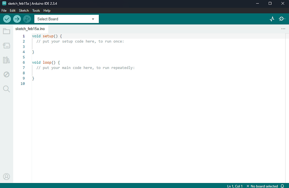
In this project, there are two functions (void). The setup() function will be executed only once when the board is powered on. In this function, the initial configurations of the board are made. The loop() function, on the other hand, will run repeatedly during the operation of the board.
Let’s create a simple code where the ESP32 writes the message "Hello World!" every second through the serial monitor.
void setup() { // code that will run just once
  Serial.begin(9600); // begins the Serial with a baudrate of 9600 bps
}

void loop() { // code that will run repeatedly
  Serial.println("Hello World!"); // print "Hello World!"
  delay(1000); // wait 1 second
}
Explaining the Code
In the setup function, which runs only once when the board is powered on, there is the following line of code.
Serial.begin(9600);This line starts the Serial monitor, or in other words, the communication between the ESP32 and the computer. The number in parentheses, 9600, represents the baudrate of the communication. The baudrate, in simple terms, is the data transmission rate. In other words, the higher the baudrate, the faster the communication between the ESP32 and the computer tends to be.
In the loop function, there are two lines.
Serial.println("Hello World!");This line sends the message "Hello World!" through the Serial. The function Serial.println() adds a line break at the end of the message. So the next message sent will be displayed on the next line. If this is not desired, you should use the Serial.print() function instead. This way, no line break will be added.
The next line calls the delay() function.
delay(1000);This function makes the ESP32 wait for a specified amount of time before proceeding with execution. The time is given in milliseconds. In this case, 1000ms = 1s, meaning the board will wait 1 second before continuing with the program.
Running the Code
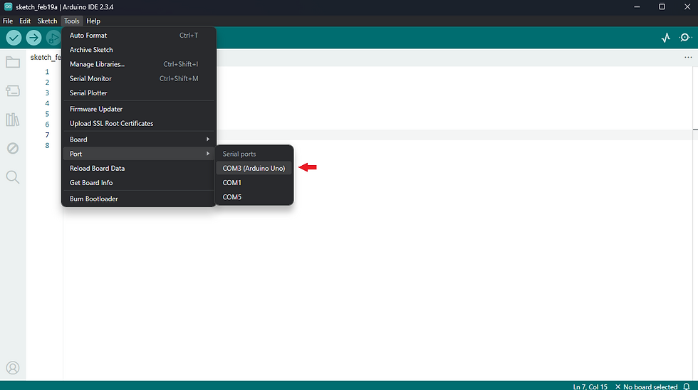
To run the code, connect your board via USB to the computer. Then, click on Tools -> Port, and a list of serial ports will appear. Select the one that represents your Arduino Uno.
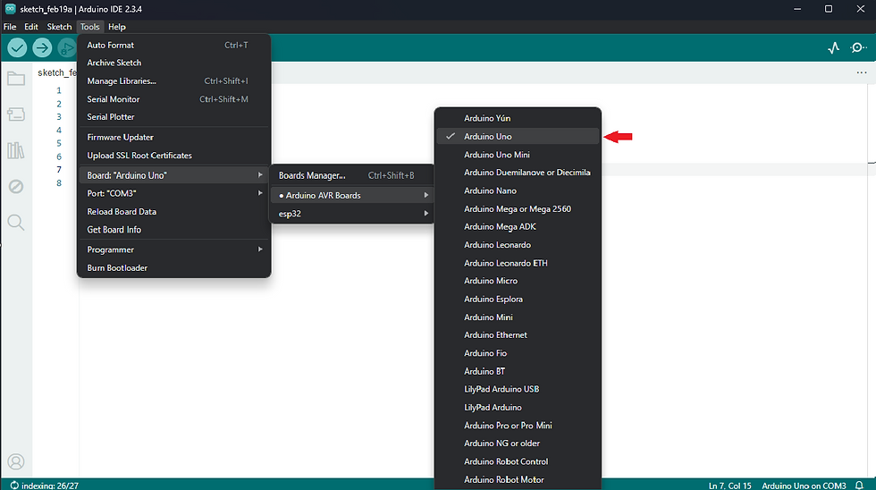
You also need to choose which board you want to compile your code for. To do this, click on Tools -> Board -> Arduino AVR Boards and select the Arduino Uno board.
Having selected the COM port and the board, you can now upload your code. Click the arrow button in the upper-left corner to transfer your code to the Arduino.

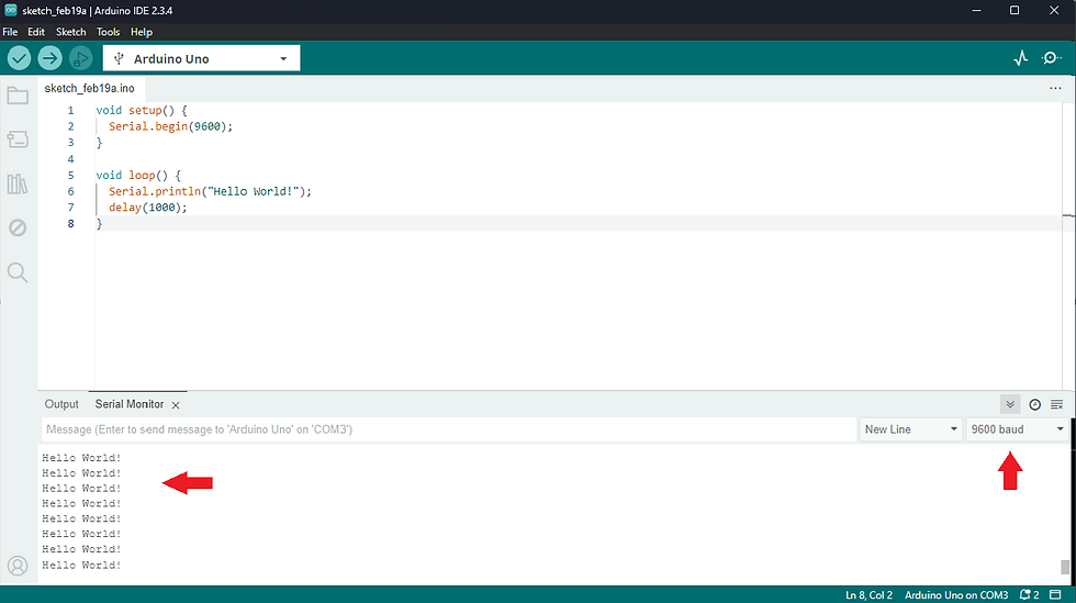
To open the serial monitor and check the messages sent by the ESP32, simply click on Tools -> Serial Monitor in the top menu.
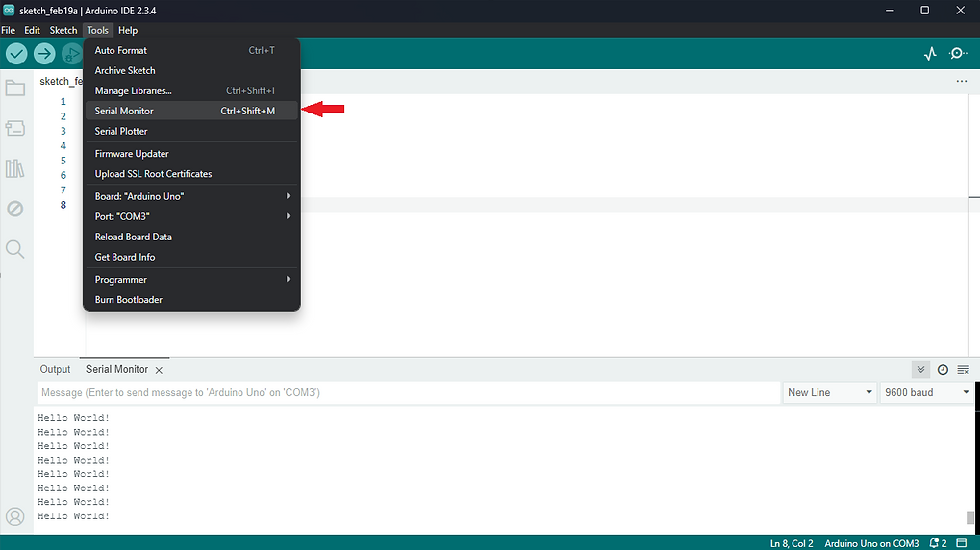
This will open the serial monitor at the bottom of the Arduino IDE. There, you will be able to see the messages appearing every 1 second, as configured in the code. Make sure the Serial Monitor is set to the same baudrate as the board. This can be configured in the right corner of the Serial Monitor tab.
Conclusions
In conclusion, the Arduino Uno is an essential tool for both beginners and professionals in the fields of electronics and programming, allowing them to explore the world of creating interactive and innovative projects. Learning to work with Arduino opens doors to developing practical skills that are highly valued in the job market, particularly in sectors like automation, robotics, the Internet of Things (IoT), and rapid prototyping.
Moreover, the accessibility of Arduino, coupled with a vast support community, makes learning more efficient and applicable to various fields. With the growing demand for increasingly integrated and personalized technological solutions, familiarity with Arduino not only enhances technical knowledge but also prepares professionals to stand out in an ever-more competitive and innovative market.


Comentários