How to use a Matrix Keypad
- automatelabonline
- Mar 5
- 4 min read

Updated: Mar 9
Matrix keypads are widely used components in electronics projects, especially in systems involving microcontrollers such as Arduino. They offer an efficient way to detect multiple keys with a reduced number of pins on the microcontroller. This is possible due to their arrangement of rows and columns, where each key is associated with a specific intersection between a row and a column.
In the context of Arduino, a matrix keypad is typically composed of a matrix of buttons arranged in rows and columns. When a key is pressed, the circuit is closed, allowing the Arduino to detect which key was pressed by reading the corresponding row and column. This approach saves input pins and makes it easier to implement interactive systems such as password boxes, controllers, and control panels without the need for excessive amounts of wire.
Additionally, libraries like Keypad for Arduino simplify the implementation of matrix keypads by providing an easy-to-use interface for reading button inputs, allowing developers to focus on the design logic without worrying about the complexity of key detection.
How Matrix Keypads Work
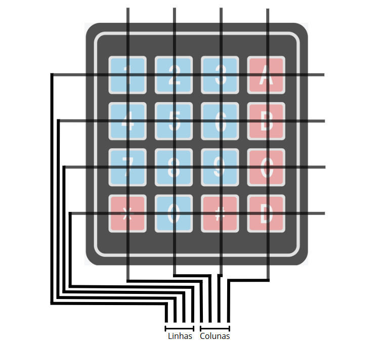
The matrix keypad is made up of wires that cross the board in the direction of the rows and columns. Each key is a button that, when pressed, joins the wires of the corresponding row and column. For example, when pressing the 2 key, the first row and the second column are in contact. When pressing the C key, the third row and the fourth column are in contact.
To perform the reading, the contact between rows and columns is measured to identify which key is being pressed. For example, if contact is perceived between row 4 and column 2, it is known that key 0 was pressed.
Project - Reading a Matrix Keypad
To read a matrix keypad using the Arduino Uno, we will use the Keypad library. To install it, simply open the libraries tab in the Arduino IDE, and search for Keypad, as shown in the image below. If you are using version 1 of the Arduino IDE, go to the top menu and click on Tools -> Manage Libraries and a window will open, in it, search for Keypad. The library's Github can be accessed through this link.

Once installed, simply connect the keypad to the Arduino as shown in the image below. The first four pins of the keypad (connected to pins 10, 11, 12 and 13 of the Arduino) correspond to the rows of the matrix keypad. The last four (connected to pins 6, 7, 8 and 9 of the Arduino) correspond to the columns.

Below is the project code.
#include <Keypad.h>

#define NUM_LINES 4 // defines the lines number
#define NUM_COLUMNS 4 // define the columns number

const char KEYS[NUM_LINES][NUM_COLUMNS] = { //create the characters matrix
  {'1', '2', '3', 'A'},
  {'4', '5', '6', 'B'},
  {'7', '8', '9', 'C'},
  {'*', '0', '#', 'D'}
};

const byte PINS_LINES[NUM_LINES] = {13, 12, 11, 10}; // lines pins
const byte PINS_COLUMNS[NUM_COLUMNS] = {9, 8, 7, 6}; // columns pins

Keypad keypad = Keypad(makeKeymap(KEYS), PINS_LINES, PINS_COLUMNS, NUM_LINES, NUM_COLUMNS); // create the keypad

void setup() {
  Serial.begin(9600);
}

void loop() {
  char key = keypad.getKey(); // read the keypad
  if (key) {
    Serial.println(key);
  }
}
Understanding the Code
Right at the beginning, the numbers of rows and columns are defined, as well as the matrix of characters that each key will represent ( keymap ).
#define NUM_LINES 4 // defines the lines number
#define NUM_COLUMNS 4 // define the columns number

const char KEYS[NUM_LINES][NUM_COLUMNS] = { //create the characters matrix
  {'1', '2', '3', 'A'},
  {'4', '5', '6', 'B'},
  {'7', '8', '9', 'C'},
  {'*', '0', '#', 'D'}
};
Further down, the row and column pins are defined. If you use different pins, simply change this part of the code.
const byte PINS_LINES[NUM_LINES] = {13, 12, 11, 10}; // lines pins
const byte PINS_COLUMNS[NUM_COLUMNS] = {9, 8, 7, 6}; // columns pins
Then, the keypad object is created, passing the keymap, pins and number of rows and columns as parameters.
Keypad keypad = Keypad(makeKeymap(KEYS), PINS_LINES, PINS_COLUMNS, NUM_LINES, NUM_COLUMNS); // create the keypadIn the loop() function , the keypad is read by the getKey() function. When a key is pressed, its corresponding character is written to the Serial.
char key = keypad.getKey(); // read the keypad
if (key) {
  Serial.println(key);
}
Additional Library Functions
The Keypad library can be explored through its repository. Here are some useful functions to use.
Detecting a Key Press
The getKey() function returns a char, which indicates which key was pressed. The function returns empty if no key was pressed.
char getKey();Detecting Keystrokes
The getKeys() function returns a boolean, which indicates whether any key was pressed or released.
bool getKeys();Detecting the Pressing of a Specific Key
The isPressed() function detects whether a specific key has been pressed. The key character must be passed as a parameter, and the function returns a boolean indicating the state of the key. It is worth noting that this function does not update the states of the keys, so it is necessary to call the ketKeys() or getKey() function first.
bool isPressed(char keyChar);Wait for a Key to be Pressed
The waitForKey() function stops code execution until a key is pressed. This function returns the character of the key that was pressed.
char waitForKey();Adding an Event for Keys
The addEventListener() function adds a function that will be called when a key is pressed. However, just like the isPressed() function, it requires the getKeys() or getKey() command to be called to update the key states. As a parameter to this function, a KeypadEvent key object will be passed, containing the character of the pressed key.
void addEventListener(void (*listener)(char));Implementing Debounce on Keys
It is possible to implement a debounce on the keys using the setDebounceTime() function. A debounce is the waiting time that the microcontroller will wait to accept new pulses. Sometimes, when clicking a key, the signal may be sent two or more times very quickly, making the Arduino understand that the key was pressed more than once. Implementing the debounce eliminates this problem.
void setDebounceTime(uint debounce);Conclusion
In conclusion, the use of matrix keypads with Arduino offers a practical and effective solution for creating input interfaces in electronic projects. Its implementation allows interaction with systems in a simple and accessible way, with a minimum number of input pins on the microcontroller, which makes it possible to develop compact and functional projects.

Comments