Exploring the PWM Pins - ESP32
- automatelabonline
- Mar 1
- 4 min read
Pulse Width Modulation is a technique used by many microcontrollers to simulate analog signals. The ESP32 has two true analog outputs (GPIO25 and GPIO26), which output a voltage between 0V and 3.3V. However, the board also offers several PWM outputs, which can be useful in many cases where an analog output is needed.
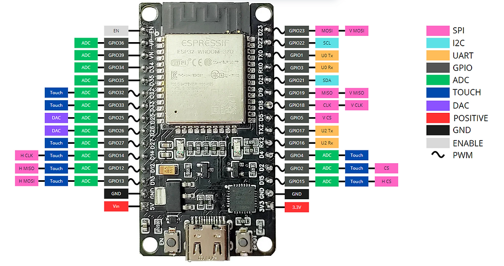
The ESP32 contains 21 ports that can act as PWM ports. However, it is only possible to use 16 PWM channels simultaneously. The image below shows the ESP32 pinout. The PWM pins are marked with a ~ symbol.
Understanding ESP32 PWM
An important term when dealing with PWM is the duty cycle . The duty cycle represents the proportion of time that the signal remains at a high level. The average output voltage of the PWM is given by the equation:
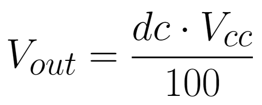
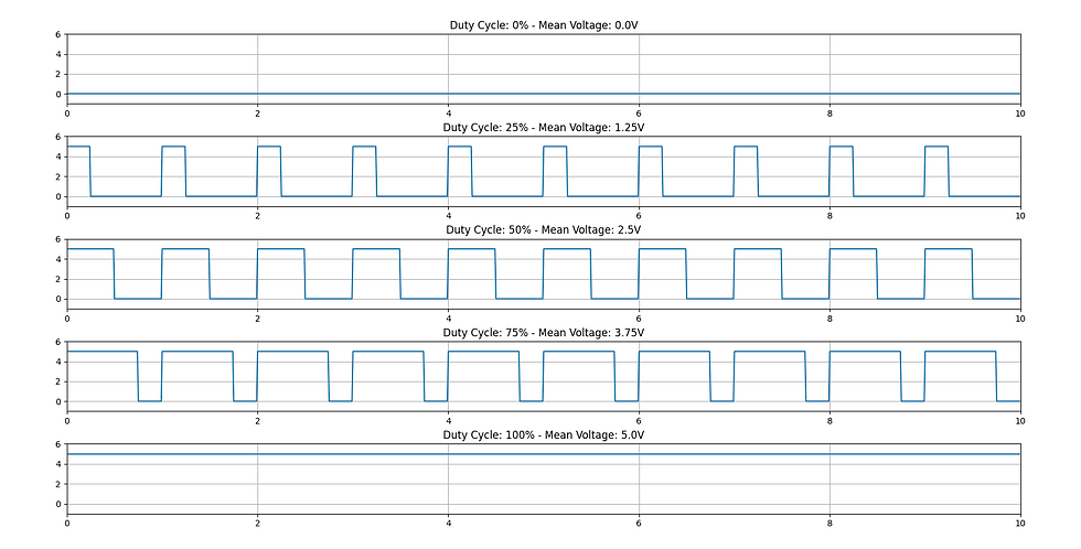
Where Vout is the average output voltage, Vcc is the high-level voltage, which in ESP32 is 3.3V, and dc is the duty cycle , in percentage. The image below shows some examples of signals for different duty cycles .
The ESP32 PWM resolution is configurable, and can be between 1 and 16 bits. In other words, there are up to 2 ¹⁶ = 65536 voltage possibilities. Since this voltage varies between 0V and 3.3V, the minimum range between voltages is:

Functions for ESP32 PWM Pins
Setting the Pin
The first step to using a pin is to associate that pin with a PWM channel. To do this, you need to use the function:
ledcAttachPin(PIN, CHANNEL);Where PIN represents the ESP32 pin number and CHANNEL the PWM channel number, which can range from 0 to 15.
The next step is to configure this channel, selecting its output frequency and resolution. This is done with the function:
ledcSetup(CHANNEL, FREQUENCY, RESOLUTION);CHANNEL represents the PWM channel being configured, FREQUENCY the frequency of the modulated signal, which can range from 1Hz to 40kHz, and RESOLUTION the number of bits that will represent the output signal, ranging from 1 to 16 bits.
Sending a Signal to the Pin
To write to the PWM pins, the function is used:
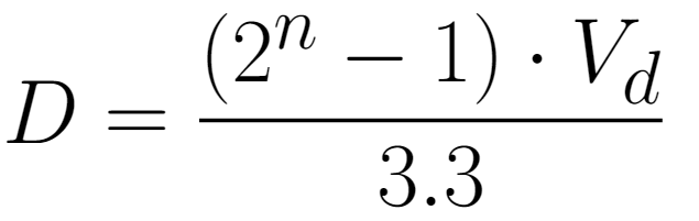
ledcWrite(CHANNEL, VALUE);VALUE is an integer that varies between 0 and 2ⁿ -1, where n is the number of bits configured in the resolution. This value represents the duty cycle that will be sent. Given a desired voltage value Vd. The value that must be filled in (let's call it D ) is given by:
Another useful formula is the value of D as a function of the duty cycle you want to obtain.

Where dc is the duty cycle given as a percentage.
Project - Controlling the Brightness of an LED
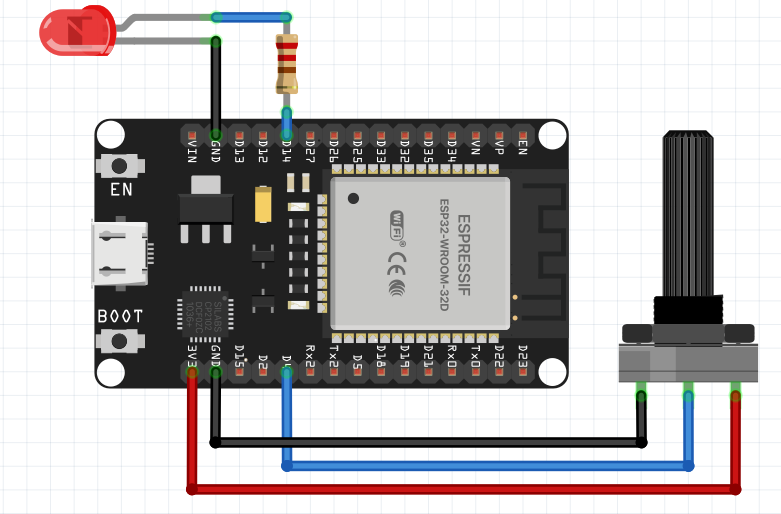
To apply the knowledge about PWM pins, we will create a project to control the brightness of an LED through a potentiometer. The image below shows the connection of the components with the ESP32. Pin 4 is used to read the potentiometer. Pin 14 is used to generate the PWM signal that powers the LED.
Below is the code for this project.
#define PIN_LED 14 // define the LED pin
#define PIN_POTENTIOMETER 4 // define the potentiometer pin
#define CHANNEL_LED 0 // defines the PWM Channel for the LED

void setup() {
  pinMode(PIN_POTENTIOMETER, INPUT); // pins configuration
  pinMode(PIN_LED, OUTPUT);
  ledcAttachPin(PIN_LED, CHANNEL_LED);
  ledcSetup(CHANNEL_LED, 1000, 12); // optional
}

void loop() {
  int ledIntensity = analogRead(PIN_POTENTIOMETER);
  ledcWrite(CHANNEL_LED, ledIntensity); // Send the signal to the LED
  delay(10);
}
Understanding the Code
First, the input and output pins are defined, along with the PWM channel that will be used. As an analog input, pin 4 is used. As a PWM output, we have pin 14, which is associated with PWM channel 0.
#define PIN_LED 14 // define the LED pin
#define PIN_POTENTIOMETER 4 // define the potentiometer pin
#define CHANNEL_LED 0 // defines the PWM Channel for the LED
Then, in the setup() function, these pins are configured. Pin 4 is defined as input and pin 14 as output. Pin 14 is associated with PWM channel 0 using the ledcAttachPin(PIN, CHANNEL) function. This channel is configured using the ledcSetup(CHANNEL, FREQUENCY, RESOLUTION) function, where the PWM frequency is set to 1000Hz and 12-bit resolution.
void setup() {
  pinMode(PIN_POTENTIOMETER, INPUT); // pins configuration
  pinMode(PIN_LED, OUTPUT);
  ledcAttachPin(PIN_LED, CHANNEL_LED);
  ledcSetup(CHANNEL_LED, 1000, 12); // optional
}
In the loop() function, the potentiometer pin is read and saved in the ledIntensity variable. Then, using the ledcWrite(CHANNEL, VALUE) function, PWM channel 0 (and consequently pin 14) receives a signal corresponding to the potentiometer reading value. Since the analog ports also read 12 bits, there is no need to make any transformations to this value.
void loop() {
  int ledIntensity = analogRead(PIN_POTENTIOMETER);
  ledcWrite(CHANNEL_LED, ledIntensity); // Send the signal to the LED
  delay(10);
}
Conclusions
In conclusion, the ESP32's PWM pins are a powerful and versatile tool for creating electronic projects that require precise signal intensity control, such as motors, LEDs, and other devices. The ESP32's flexibility in terms of configuration and the high precision of its modulation make it an excellent choice for a wide range of applications.
Furthermore, its easy integration with other microcontroller functionalities, such as Wi-Fi and Bluetooth, further expands its potential in automation and Internet of Things (IoT) projects. By exploring and understanding how the ESP32's PWM pins work, developers can take advantage of its capabilities to create more efficient and dynamic systems, providing innovative and high-performance solutions.
Comments