Exploring the PWM Pins - Arduino Uno
- automatelabonline
- Feb 22
- 4 min read

Pulse Width Modulation is a technique used by many microcontrollers to simulate analog signals. Creating truly analog signals may not be feasible in devices like the Arduino, where cost is a key factor. Therefore, one way to work around this issue is through Pulse Width Modulation, commonly known as PWM.
Pulse width modulation involves alternating the output between high and low levels at a high frequency. On the Arduino Uno, this frequency is by default 490Hz, except for pins 5 and 6, which operate at 980Hz. Since this oscillation occurs very quickly, the output behaves as if it were at a voltage between the high and low levels.
On the Arduino Uno, the pins with PWM functionality are marked with a ~ next to the pin number. There are 6 PWM pins: 3, 5, 6, 9, 10, and 11.

Understanding the PWM on Arduino Uno
An important term when dealing with PWM is the duty cycle. The duty cycle represents the proportion of time that the signal remains at a high level. The average output voltage of the PWM is given by the equation
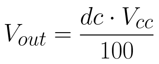
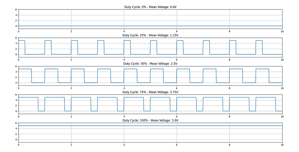
Where Vout is the average output voltage, Vcc is the high-level voltage, which on the Arduino Uno is 5V (except when powered with 3.3V), and dc is the duty cycle, in percentage. In the image below, some examples of signals for different duty cycles are shown.
The PWM resolution of the Arduino Uno is 8 bits. In other words, there are 2⁸ = 256 possible voltage levels. Since this voltage varies between 0V and 5V, the minimum voltage step is

Functions for PWM Pins
The function for writing to the PWM pins is
analogWrite(PIN, VALUE);Where PIN represents the PWM pin and VALUE is an integer between 0 and 255 that represents the voltage to be generated on the pin. 255 is the maximum value, that is,5V. This integer (let's call it D ) can be calculated using the equation below.
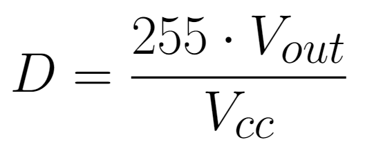
Where Vcc represents the maximum voltage (5V) and Vout is the desired voltage for the pin. So, for example, to apply 2.8V to the pin, you would do
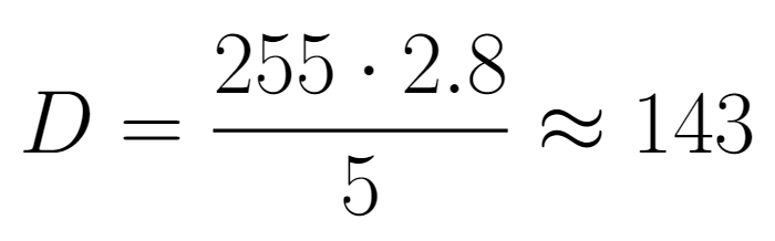
So, the command sent to the Arduino should be
analogWrite(143);
Project - Controlling the Brightness of an LED
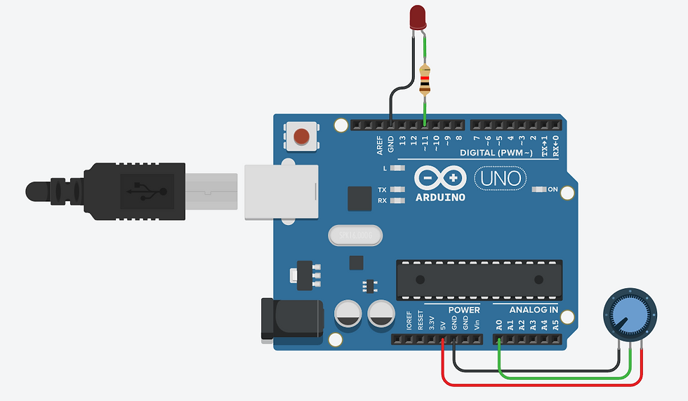
To apply the knowledge about PWM pins, let's create a project to control the brightness of an LED using a potentiometer. The image below shows the connection of the components to the Arduino. Pin A0 is used to read the potentiometer. Pin 11 is used to generate the PWM signal that powers the LED.
Below is the code for this project.
#define PIN_LED 11 // defines the LED pin

void setup() {
  pinMode(PIN_LED, OUTPUT); // Set the pin as Output
}

void loop() {
  int potentiometer = analogRead(0); // Read the Potentiometer
  int ledIntensity = map(potentiometer, 0, 1023, 0, 255);  // convert from 10 bits (0 to 1023) to 8 bits (0 to 255)
  analogWrite(PIN_LED, ledIntensity); // Send the signal to the LED
  delay(10);
}
Understanding the Code
The first step is to define pin 11 as an output, this is done in the setup() function.
#define PIN_LED 11 // defines the LED pin

void setup() {
  pinMode(PIN_LED, OUTPUT); // Set the pin as Output
}
Inside the loop() function, the potentiometer is read and saved in the variable potentiometer. This variable serves as input for the map() function. This function maps the value from one range to another. In this case, the analog pin reading is 10 bits, so the value returned will be between 0 and 1023. However, the PWM write value is only 8 bits, so it ranges from 0 to 255.
The map() function adjusts the value to this new range. For example, if the read value was 511 (halfway between 0 and 1023), the output of the function would be 127 (halfway between 0 and 255). The map() function follows this format:
map(VALUE, IN_MIN, IN_MAX, OUT_MIN, OUT_MAX);Where VALUE represents the input to be transformed, IN_MIN and IN_MAX are the input ranges, and OUT_MIN and OUT_MAX are the output ranges. In the example above, where the potentiometer is read and this value will be passed to a PWM, the code looks like this:
int potentiometer = analogRead(0);
int ledIntensity = map(potentiometer, 0, 1023, 0, 255);
analogWrite(PIN_LED, ledIntensity);
Conclusions
The PWM outputs of the Arduino Uno provide a practical and efficient solution for controlling devices that require varying signal intensity, such as motors, LEDs, and servos. The flexibility of the Arduino Uno, with its 6 PWM outputs, opens up a wide range of possibilities for automation projects, lighting control, and even more complex control systems.
Understanding how these outputs work and their application in real circuits is essential for those looking to expand their skills in electronics and programming, enabling the development of innovative and efficient prototypes. Moreover, the ease of integration with other modules and the vast community of developers make the Arduino Uno an excellent choice for both beginners and professionals.


Comments